![[Teseo2]](/images/teseo.png)
![[INGV]](/images/ingv_world.png)
|
|
|
[
News |
About Teseo2 |
Filters |
Downloads |
Documentation |
Mailing Lists |
Getting Involved |
Bugs and Issues
] [ Teseo2 from Source | ] [ ] |
Teseo VectorisationThe digitisation procedure involves usually:
The standard seismogram digitisation process is shown in the flow chart of figure 1. The Image process produces a pixel coordinates sequence belonging to the trace (rough digital) and the Correction process transforms it in a time domain seismic signal (final digital). This latter stage needs some instrumental parameters a priori known or obtainable from the seismogram image.
Within the Image process we have introduced an intermediate step that produces a vectorial representation of the seismic trace on the image, see figure 2. Vectorial representation is more compact than the pixel coordinates sequence and, in addition, it allows more interactivity with the graphic software.
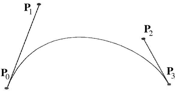
The seismic trace can be represented by a piecewise cubic Bézier curve, that is, a concatenation of cubic Bézier segments. This vectorial description of the curve needs the definition of 4 points for every Bézier curve (see figure 3). It also allows for an unlimited level of detail in resampling.
Vectorisation methods
|
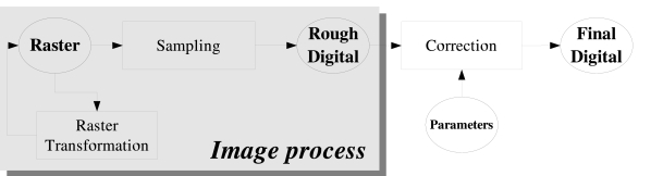 Figure 1.
Flow diagram of the standard digitisation process.
Figure 1.
Flow diagram of the standard digitisation process.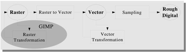 Figure 2. Flow
diagram of the Teseo image process. Note that this approach introduces the vector
transformation phase before obtaining the rough digital output.
Figure 2. Flow
diagram of the Teseo image process. Note that this approach introduces the vector
transformation phase before obtaining the rough digital output.